Important!
- Details such as overlap joints, fastenings, pipe and cable pass-throughs, or for example beams, should be sealed airtight with approved aids for the inner climate shield system, such as tape (T-Flex), grommets, sealant, or double-sided tape. See system description!
- Mechanical fastening (staples/nails) of the foil must always be galvanized. Fastening with staples should be taped (with T-Flex) for optimal airtightness.
- Consider the attachment of the climate screen. The foil should be fixed with a minimum center distance of 600 mm on a solid frame structure. Additional fastening is required for folds or extensions.
- Connections/seals of the foil between different types of construction materials, where the foil is attached, for example, between wood and concrete or steel/sheet metal, should be done with extra foil in folds/waves just before the connection (approximately 50 mm).
- Creases in the foil that meet the taped joint across should be sealed extra with at least 200 mm of taping over the taped overlap and along the crease (100 mm in each direction). This extra taping should follow the bottom and top of the crease!
- An internal climate screen should always be mounted offset into the outer wall (maximum 1/3 of the total insulation thickness). The reported installation should/can be equipped with an insulated zone inside the foil (serves as an installation zone for electricity, etc.).
- During installation and in colder seasons, consider the risk of condensation on the inside of the external wind barrier. With the insulation in place, this risk increases significantly, so a quick installation of the internal climate screen is protective and preferable.
- Store and keep packaged/protected from sunlight (UV radiation) or consistently higher temperatures (>35°C). The film has freely exposed (not built-in) UV protection that corresponds to the construction time (< 6 months).
Roof
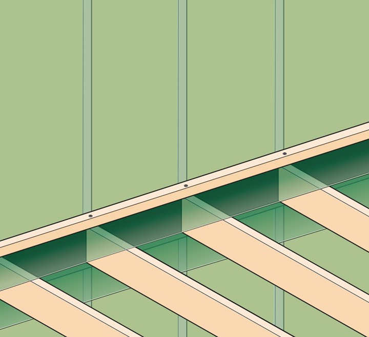
The tightness improves if interior walls are erected in connection with the above assembly so that the vapor barrier is placed between the floor structure and the interior wall. The foil is generally attached to the underside of the roof beams with galvanized staples and with a drop around (200 mm) towards the walls. A sparse panel from below fixes and secures the foil definitively up against the roof beams.
NOTE! When used in roofs/floor structures, consider the Swedish Work Environment Authority's regulations on fall-through protection where Teccas air and vapor barrier (X-Foil Duo) is recommended. When installing in low-slope roof constructions (substrate of profiled sheet metal), the air and vapor barrier should be placed so that a solid substrate is always present under the foil joints. Either from a flat sheet or preferably from a first layer of insulation (offset vapor barrier, installation zone). However, with a maximum thickness corresponding to 1/3 of the total insulation thickness. All joints must be taped!
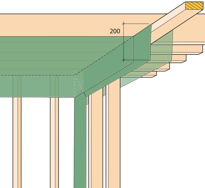
Ceiling – Along the rafters
1. Roll out the foil and cut to the desired length. Always allow for at least 200 mm overlap. Assume that 200 mm should be folded down on exterior walls and connected.
2. Start at the wall and attach and roll the foil in the same direction as the beams. The overlap and joint to the next foil sheet should occur under the beams (200 mm). The overlap joint should be stretched completely along the beam and clamped across with sparse paneling or equivalent (c-distance max 400 mm). Sealing of the joint should be done with Sealing Tape T-Flex.
3. Insulation is placed tightly on top of the foil and between the rafters so that no unnecessary air spaces are formed.
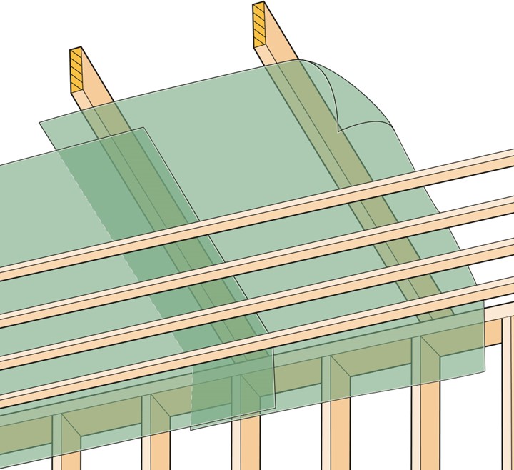
Roof – Across the rafters
1. Roll out the foil and cut to the desired length. Always allow for at least 200 mm overlap. Assume that 200 mm should be folded down on exterior walls.
2. Start at the wall and attach and roll the foil across the roof beams. The overlap and joint to the next foil sheet should occur under the beams (200 mm). The overlap joint should be fully stretched and clamped with sparse paneling or equivalent in the center of the overlap (100/100 mm). Taping of the joint should be done with Sealing Tape T-Flex and with extra sparse paneling fastened/clamped along the entire joint taping.
3. Insulation is placed tightly on top of the foil and between the roof beams so that no unnecessary air spaces are formed.
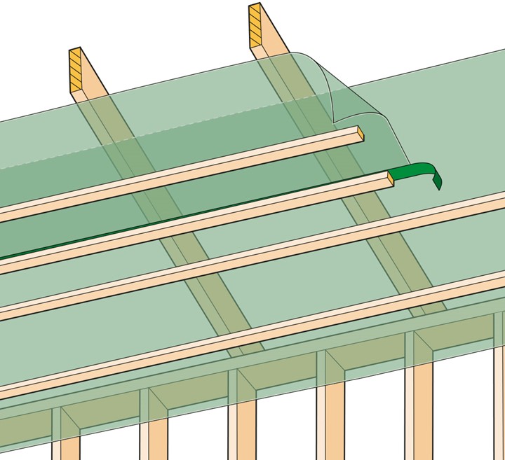
Wall
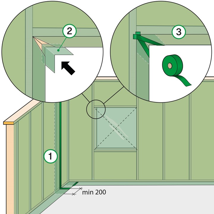
Installation of load-bearing interior walls should be done first, with a foil strip applied at the connection to the outer wall's frame (see the first image ROOF). Taping of all joints is done with Sealing Tape T-Flex for complete tightness and durability. Fastening and joining to concrete is done with Joint Tape T-Duo Concrete.
1. Roll out the foil and cut to the desired length. Always allow for at least 200 mm overlap.
2. Attach the foil to the top edge of the wall/hammer beam. The overlap occurs from the ceiling down onto the wall foil. The joint should be clamped between a stud and another stud or sheet material
5. Be extra careful with the attachment points around window and door openings. In frame openings, the easiest way is to make a cross-cut (Alternative cutting can be done and the taping should then be equally airtight) of the foil, from corner to corner. The foil is then folded out into the frame's recess and fastened with staples or tape. Before fastening, extra foil pieces (square) with folds should be placed under the flaps in each corner so that they are completely covered with foil (Image detail 2.). Edges and joints are taped (T-Flex) (Image detail 3.). The foil piece can be replaced with tape or sheets of tape (T-Flex).
3. Secure the foil firmly to the wall (with galvanized staples or battens with a minimum c-distance of 600 mm or double-sided Splice Tape T-Duo). The foil should be finished so that it covers the inside of the wall's sill and is folded out onto the floor with at least 200 mm for overlapping the floor's foil. Alternatively, the foil is finished without overlap with tape against the sill (T-Flex) or with T-Duo Concrete down to any concrete slab.
4. Vertical joint should be executed clamped over the standing stud with an overlap of at least 200 mm. The overlap is taped (T-Flex) (Image detail 1.).
Floor
1. Roll out the foil and cut to the desired length. Always allow for at least 200 mm overlap.
2. The film should start and end in overlap/joint around the outer edges of the floor surface. This is done on the flat substrate at the edges with the connecting climate screen/film from the wall. For any interior wall, the termination applies to the wall's sill. Taping of all joints is done with Sealing Tape T-Flex for complete tightness and durability. Fastening and joining to concrete is done with Joint Tape T-Duo Concrete.
When used on a concrete slab, it is assumed that the construction moisture is temporary and limited. For larger amounts or additional moisture, a denser product than a vapor barrier should be used (a moisture barrier). In case of doubt, usage should be preceded by a moisture analysis. Usage on a concrete slab involves placement directly on the concrete surface, and the concrete should be drained and insulated on the underside. A concrete slab insulated on the top always has poorer conditions to function with moisture protection above!
Be careful and inspect the floor surface before installation. The surface should be cleaned of, among other things, stones, sand, sharp particles, or other loose debris. On concrete surfaces, it is also important to remove organic material! Handle the foil gently during installation to avoid damage. Cover for protection if necessary!
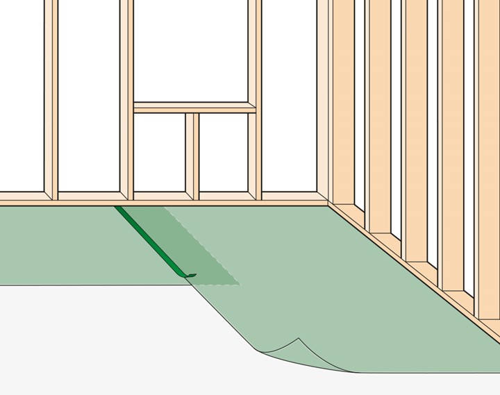
Sealing in intermediate floors occurs with Tecca Floor Sealing installed in each beam compartment (c-measure 600mm). The vapor barrier from the outer wall above and below is joined to the Floor Sealing and airtight.
See full assembly instructions: Floor sealing for moisture-protective solutions, among others - TECCA
Options assembly (no image) can be done with a cut vapor barrier from the outer wall above with respect to the beams' c-spacing. Adjust the size of the foil so that the fold ends at the bottom of the floor structure.
The foil is first unfolded on the beams in the joist and Y-cut lying on the beams. Then fold the foil down between the beams. Secure and staple each flap around the beams. Tape carefully around each beam with Sealing Tape T-Flex according to the installation instructions for T-Flex (see Beam Penetration). From below, the vapor barrier of the underlying floor should be pulled up and out under the beams. Seam tape the foil underneath with the one from above. All overlaps and seams are done with taping (T-Flex).